© Inovonics, 2011 - www.inovonics.com
EN1247 EchoStream® ShatterPro™
Glassbreak Transmitter
Installation and Operation Manual - 04864E
1 Overview
The EN1247 is an acoustic glassbreak sensor that transmits digital RF
messages to Inovonics Wireless receivers. The glassbreak sensor module
is the wireless ShatterPro, manufactured by GE Interlogix, Inc. The
wireless transmitter module is manufactured by Inovonics Wireless
Corporation.
1.1 Inovonics Wireless Contact Information
If you have any problems with this procedure, contact Inovonics Wireless
technical services:
• Phone: (800) 782-2709; (303) 939-9336
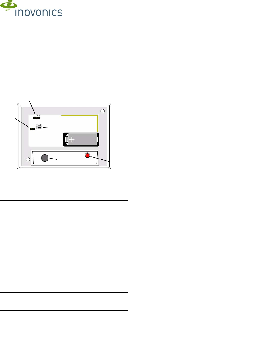
Fig. 1
EN1247 components
2 Installation and Startup
Note: The tamper pins are used to test the EN1247. If the jumper is
removed from the tamper pins, the unit will remain in a state of tamper, and
will not be operational.
2.1 Install the Battery
Before installing the EN1247 glassbreak transmitter you will need to install
the battery. To install the battery:
1. Press the housing release tab on the bottom of the EN1247 housing;
pull the housing apart.
2. Install the battery.
2.2 Select Frequency Band
EchoStream products are able to use a range of radio frequencies, and
must be configured for your geographic area. To configure the EN1247:
1. Place a selection jumper on the appropriate frequency band selection
pins.
• Place the jumper on the right two pins to select 921-928 MHz for New
Zealand.
• Place the jumper on the left two pins to select 915-928 MHz for
Australia.
• Leave the jumper off the pins to select 902-928 MHz for North
America.
Caution: When pressing the Reset button, make sure you don’t also touch
the frequency band selection pins. Touching the frequency band selection
pins while pressing the Reset button can inadvertently set the EN1247 to
the wrong frequency band.
2.3 Register the Transmitter
EN1247 transmitters must be registered. Refer to receiver, network
coordinator or control panel installation instructions to register the EN1247
transmitter. Press Reset when prompted to register the transmitter.
Caution: The EN1247 should be tested after registration to ensure
operation. To test the EN1247, activate each of the conditions and ensure
an appropriate response.
2.4 Mount the EN1247
1. Use the provided anchors and screws to mount the EN1247, paying
careful consideration to the following best practices:
• To avoid false alarms, install the unit as a perimeter zone that is
armed only when the perimeter doors and windows are armed.
Installing the unit as a 24-hour zone can create false alarms.
• Mount the EN1247 at least .91 m (3ft) from the window to be
monitored, but no more than 7.62 m (25ft) away.
• Mount the EN1247 at least 1.2 m (4 ft) away from noise sources
(televisions, speakers, sinks, doors, etc.).
• Mount the EN1247 so that it is in direct line of sight of all windows to
be protected.
• The best location for mounting the EN1247 is on the wall opposite of
the window to be protected. The EN1247 may also be mounted on the
wall adjoining the window to be protected, or on the ceiling.
• The glass should have the following dimensions:
- Height and Weight: 0.3 m x 0.6 m (1 x 2ft) or larger
- Plate thickness: 2.4 mm to 6.4 mm (3/32" to 1/4")
- Tempered thickness: 3.2 mm to 6.4 mm (1/8" to 1/4")
- Wired thickness: 6.4 mm (1/4")
- Laminated thickness: 3.2 mm to 6.4 mm (1/8" to 1/4")
• Avoid glass airlocks and glass vestibule areas, noisy kitchens and
residential car garages.
• Avoid rooms smaller than 3 x 3 m (10 x 10 ft), such as small utility
rooms, stairwells and small bathrooms.
• Because the unit is not hermetically sealed, avoid humid rooms.
• Avoid rooms where white noise, such as air compressor noise, is
present. (A blast of compressed air may cause a false alarm.)
• Avoid rooms with noise insulation or sound-deadening drapes or with
closed, wooden window shutters inside.
• Avoid placing the EN1247 in the corner of a room.
2.5 Test the EN1247
The EN1247 should be tested following installation.
1. Remove the jumper from the tamper pins to test the transmitter. This
should cause a tamper fault.
2. To confirm the sensor has power and the microphone and circuit board
are functioning, clap your hands loudly in front of the sensor. The LED
will blink twice, but the alarm will not trip.
3. For full functionality testing, use the Sentrol 5709C acoustic glassbreak
tester to switch the unit into test mode and simulate alarm conditions
via sonic bursts.
3 Specifications
Dimensions: 108 x 80 x 43mm (4.2 x 3.1 x 1.7")
Typical battery life: 2 years
Battery (BAT604): 3.0V lithium Panasonic CR123A or approved
equivalent
Operating environment: -20° to 60°C (-4° to 140°F), noncondensing
RF frequency range: 902-928 MHz
Microphone: Omnidirectional Electret
4 Television and Radio Interference
This equipment has been tested and found to comply with the limits for a
Class B digital device, pursuant to Part 15 of the FCC Rules. These limits
are designed to provide reasonable protection against harmful interference
in a residential installation. This equipment generates, uses and can
radiate radio frequency energy and, if not installed and used in accordance
with the instructions, may cause harmful interference to radio
communications. However, there is no guarantee that interference will not
occur in a particular installation. If this equipment does cause harmful
interference to radio or television reception, which can be determined by
turning the equipment off and on, the user is encouraged to try to correct
the interference by one or more of the following measures:
• Reorient or relocate the receiving antenna.
• Increase the separation between the equipment and receiver.
• Connect the equipment into an outlet on a circuit different from that to
which the receiver is connected.
• Consult the dealer or an experienced radio/TV technician for help.
A Mounting holes B Frequency selection pins C Tamper pins
D Reset button E Microphone F Sensor LED
 (2 pages)
 Manymanuals.com
 Manymanuals.de
 Manymanuals.fr
 Manymanuals.it
 Manymanuals.pl
 Manymanuals.cz
 Manymanuals.es
 Manymanuals-pt.com
Comments to this Manuals